I used more gorilla snot to attach the model ID plates to the starter cover.

Those plates are a bit beat up. Some day I will replace them. But this week I finally got around to to adding up all the project expenses so far. Ouch.
I told some of my friends at work that there is indeed a price tag on sentimental value. Bryan told me before I started to take my seriously considered budget and double it. He went through this restoring and hot rodding a 1969 Camaro. I shook my head and said, “that can’t be right. This restoration should cost me between $4K and $5K.” He was dead right. My spent and to-go expenses total somewhere north of $9K! $1K of that is non-resto cost (shipping the bike & DMV fees). Say another $1K is highly optional or upgrade items (H4 headlight, charging system upgrade, stainless headers & pipes, EZ clutch, Stan’s ignition lock conversion). That still leaves me with about $7K in direct restoration expenses. And I did everything on my own labor except paint, powder coat, wheel spoking, speedo/tach repair, and head/cylinder resto.
The part about sentimental value is I would have come out ahead if I had started with a nice running or partially restored bike. I’d read that many times before. Always buy the nicest vehicle you can find to restore. But if you read my Origin post you know why it had to be THIS bike, left outside, in the rain, for years. I still might have been time-and-money ahead if I bought a parts bike (e.g. transplant a running engine). That’s the path not taken, so maybe not. I’ll try to detail my expenses in a future post.
So you can understand why I didn’t run out and buy new model ID plates. There are a surprising number of cosmetic issues remaining, parts to replace, but maybe I notice them more than you will if you see the bike.
That’s enough crying in my beer. Here are new points mounted on the bike.

The arrow points between the two posts used to lever the points gap for adjustment. I still think I’ll be going to electronic ignition but I figure I should get the beast running properly on the stock system first. That will make it easier to deal with ignition failure on the road later plus most of the electronic conversions make kick starting inadvisable. They can spark at the wrong time and kick-back. Many folks say the best way to keep your kick starter in good shape is not to use it (and the engine case can be damaged when it breaks). But kick starting is too cool.
Here’s a view with the mechnical advance mounted.

The arrow is at the points gap. Clymers says to set new points to a maximum-gap position because the plastic bar that rides on the advance camshaft will quickly wear down, reducing the gap. Sounds like a recipe for rough running (big gap) and I’m scared so I set it most of the way open, well past the 0.40 mm max gap specification. By the way, many sources warn against overtightening the nut that holds the advance in place.
Hey look. A new condenser.

See the cut-away clamp that holds it? The new one came with a solid clamp but my old clamp was fine. Just a note for you purists.
Here’s the drive shaft-to-transmission connection I griped about before.

That is a tight working space!
Here is Ed Korn’s torque wrench extension (on my wrench) for finishing up in there.

I’d say the hardest part was starting the bolts.

There is not enough room to swing them freely into place. You have to wrestle with the rubber boot and lever the bolts in. And you have to rotate the connection to stay in a work-zone. This is also a good place to use 12-point wrenches (12 point bolts). My bolts are the “older” style that have a lock nut and are not threaded all the way to the bolt head.
Rotating the connection I came up against an issue I mentioned before. My engine was awfully hard to turn. To get the connection to rotate I had to engage the clutch by levering a big screwdriver with a cheater pipe and spin the rear wheel at the same time.

And eventually, swing arm boot done and clamped!

I found out why the engine was so tight. Turns out my tranny was essentially locked in position. The only way I was getting any engine rotation was by getting enough torque into it to slip the clutch! I have no idea why my tranny was locked and I figured I might have to take it off again for service. But first I filled it with oil. I was thinking maybe corrosion had it stuck and I might be able to break it free.

This picture is just a reminder to myself that I filled it. Then I rocked the rear wheel back and forth. I was starting to sweat, thinking of the effort required to pull the tranny (again) and the cost of rebuilding (FYI, $625 flat rate at Motor Works). Should I call Joe? Not much happened until I went to remove the alternator bolt which I had mounted only to rotate the engine. Then the engine suddenly spun easily in reverse. It spun easily enough that I had to use a strong impulse to break the bolt loose! After that the forward direction was fine. I could easily turn the engine with the kick starter. Woo-hoo!
I got to thinking maybe I should add fluid to the other driveline sections, lest they corrode or I just forget to do it. The arrow here points to the driveshaft oil fill port.

That made a mess because it would not accept oil at the rate I wanted to feed it. The next arrow points to the rear end oil fill port.

I got the side stand spring mounted using just a vice grip.

Centerstand springs are still to-be-done. I had the bike roll forward off the centerstand twice this week while wrenching on something! Fortunately I caught it both times. The factory stand is a bit flimsy and the bike wobbles around if pressed. Must be why the Reynolds ride-off stands are such popular upgrades? People swear by the Brown side stand too. Note the side stand is one of those self-retracting designs. So if you sit on the bike you have to be careful not to let it pop up if you are going to step off immediately (like if someone else just sits your bike). I think Duane’s site mentions I should be able to adjust the side stand spring keeper so it stays in the down position so I’ll have to try that later. I don’t see the keeper motion he mentions but I’ll try harder later.
I got the starter back in.

A 12-point wrench is absolutely necessary (13 mm if I recall correctly) because of the very short angle and space available to work in. I didn’t have to borrow Joe’s s-curved one like I did when I took it out (I posted on this way back when).
Here’s a good photo of the flap on to of the crankcase breather valve.

This device is only present in made-for-USA /5’s as a smog reduction device. Unburned hydrocarbons pressurized in the crank case burp out of this and through a tube back into the air filter. I have no idea how much it reduces emissions but it makes for one more thing to fail on the bike.
Here are some lengths of new fuel line I cut to match the old lengths. These are cloth-wrap style instead of gloss rubber style. This bike actually had a mish-mash of both on it before.

There is a tee on both sides of the tank and a cross-over connecting both fuel petcocks. In theory it only takes one open petcock to feed both carbs but in practice one petcock may not flow enough gasoline at sustained higher RPM.
Here’s a view of the right side of the air box and that breather valve fully assembled.

Here’s the new air filter.

Yep, expensive.
Here’s the airbox fully assembled, with the choke lever mounted.
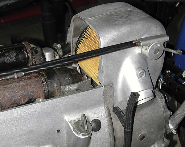
The right side airbox cover is not mounted 100% correctly. There is a piece of metal that, I think, helps hold the air filter in place. Tht is interfering with the cover and I haven’t found the right positioning to fix that yet. So there is a 1/16″ panel gap right now. I tried a few times but now I’m frustrated, so time to stick-and-move.
I made some progress on the wiring. Here’s the new and old starter relay.

The arrows point to some terminal ID markings on the old relay that are completely missing on the new one. All you can see is a potting material on the new one. Fortunately I found a visual wiring reference in the 5 United archives. Otherwise I’d sure be SOL. None of the other schematics I have show the actual terminal layout. And I have schematics from five sources — Haynes, Clymers, Prospero’s Garage (laminated), and two from on-line sources (other kind owners). Note all references say the 1973 /5’s should have two fuses but this bike had no fuse. Go figure. I’ll add fuses somewhere along the line, at least a main fuse at the battery. An unfused bike sounds like a meltdown waiting to happen.
Anyway, I’m getting a taste of the agony ahead of me in wiring. Someone get me an aspirin! Make that a Percodan.
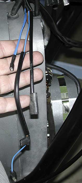
Here’s some of the front end wiring.

I needed to use an ohm meter to figure out which ground wire went to the starter. But you can see I have the starter cover on and I know the entire bundle of wires that goes to the front of the engine. I’ve got a few more bits and pieces of wiring identified but there remains a vast uncharted territory. I’m saving the headlight guts for last but we’re plunging on.
Some parts, like the tail light, have terminal markings that match up with a schematic. The arrows point to the numbers.

Here’s a small section of the schematic from the Haynes manual (buy your own, they deserve the income). Since that manual is slim and generally weak it was a shock to find it was the easiest to read because of better printing (color clarity).

The arrows point to the matching terminal numbers. Too bad so few electrical parts on the bike have terminal markings! Here is the end result and I expect it to work right the first time.

Curiously, there is a mix of spade connectors and bare wire spring clamps. The new OEM harness matches exactly, no additional spade crimping required. I bundled the whole thing up and the tail light is complete. Unfortunately the outer lens is cracked (see arrow below).

I don’t think I did it but I didn’t notice it before. This is something I’ll pay (through the nose) to replace immediately.
This photo shows tie wraps routing the harness to the oil pressure and neutral indicator switches.

I generally puttered around making connections and before I knew it, the whole back end of the bike harness was done, everything behind the headlight excluding the battery (don’t have one yet) and charging system connections. Some routings are strictly best-guess, trying to avoid moving or hot parts. I did not run the rear harness through the sub-frame. I had a bitch of a time getting the old one out and I’ve seen them routed just inside the sub-frame rail on other bikes. It looks clean enough.
Well, since most of the harness is done it was time to install the charging system upgrade. You may recall I fried my original rotor removing it. Between that and wanting a new diode board (one of the common failure points) it was not a huge financial leap to one of several upgrade kits. I anticipate increased winter electrical demands (electric clothing) on a unfaired bike. Motorrad Electrik’s Omega kit has the advantage of being essentially a beefed up version of the original (better-wound rotor, rugged diode board) so if it fails you can get repair parts at a BMW dealer. I decided to try the new kid on the block, Euro Motoelectric’s EnDuraLast kit. A few people have reported positive results and I found no negative reports. Only some traditionalists who don’t like not being able to fix it with BMW parts down the road. The truth is if you have a major charging failure on the road you can get home by strapping a charged car battery on your seat (especially since /5’s can be run with the headlight off).
Instead of rotating a wound coil inside of static magnets it uses a rotating magnet and a static coil. It does away with the sliprings (I hate slip rings). It does away with the diode board and regulator (now a single box not under front cover). It puts out more power across all RPM (they claim 280 W at 2K RPM, 400 W at 5K RPM). They make two sizes. For the /5 make sure you get the 105 mm, not the 107 mm (clear at http://www.euromotoelectrics.com/index.html).
Here is my kit.

The kit is very thorough, including Posi-Lock connections and heat shrink tubing. I used Posi-Locks in my FJR and I like ’em a lot (http://www.posi-lock.com/index.html). They can be re-used and the only complaint one could have is they are a bit bulky.
Note that the rotor and rectifier/regulator are both Ducati parts.

Cool! I always wanted a Ducati. Presumably I could get repair parts from a Ducati dealer?
Here is the rotor installed.

Here is the stator mounted.

Here are four connections under the front covere that are obsoleted by this new system.
I will wrap them up in waterproof silicone tape and hide them under the tank so I could revert to the original system without splicing these back into the harness. It was a bit of doing to separate these from the bundle going into the front cover and insert the replacement power line from the new stator. You want to re-use the odd rubber grommet at the top of the cover.
Check out the clean wiring under the front cover. They even provide a wire clamp that screws to one of the diode board posts.

Coming through that top grommet is only the stator bundle, condensor ground, and two wires for the starter. Well that’s as far as we get this time. I still need to mount the new rectifier/regulator. I’ll probably hide it under the gas tank. Air flow is better back by the battery but it would be visible (/5 SWB does not have side panels). And it says Ducati on it. Under the tank would still be a big step up from trapped inside the unvented front cover.
Instead of ending with my own version of Speed TV’s Wind Tunnel (Formula One ran today in Hungary and was newsworthy), I need to post a screed against a local computer chain. A couple of years back I bought a Fujitsu laptop from Notebookshop.com. That’s actually a set of four brick-and-mortar stores in So Cal. For a while now it has been failing the Windows Genuine Advantage test and that means I can’t upgrade Internet Explorer. Yeah, save your breath. I use Mozilla too. But IE is the one I run for maximum compatibility these days. Anyway, I don’t have the OS disks since it was upgraded from Win XP Home to XP Pro at the store when I bought it. So I trudged down to the store and chat with their tech. He looks up the records and informs me that it was a “courtesy” upgrade to XP Pro, meaning it is not a legal copy! I’m a bit flabbergasted. This chain’s parent company has been around for 16 years and obviously this chain itself has some staying power (some years at least). Not only is the OS, well, pirated, but they want to charge me more to restore the original XP Home OS than Microsoft wants to charge me to make my XP Pro legal! I press the store manager but get no satisfaction. Fine. I told the tech I’d be informing Microsoft’s legal department and left in a huff.
I took my laptop home and used Fujitsu’s own recovery program to restore it to factory condition. They use a hidden partition on the hard drive and that system is slick. Worked like a charm. I just had to endure 80+ Windows updates to XP Home over my DSL line and reinstall all the other software I use. I’m not a good pirate. I buy every single piece of software I use for hobbies (e.g. MS Office, Lightwave, Photoshop, Premiere, AutoCad LT). Quick side-note, check out Open Office if you don’t want to pay Microsoft for their Office suite. It is the absolutely free open source evolution of Sun Microsystems’ Star Office and it works well. So the end of the story for now is I e-mailed Microsoft’s piracy address and they gave me their auto-response. I hope the 800 pound gorilla lands on Notebookshop.com but I’m not expecting much. Except for me to bad-mouth Notebookshop.com at every opportunity. Pirates! Arrrrr!

Hi,hellow!
By chance I found your blog in web from Japan.
Now I’m also try to repair selfstarter….But I have no idea to unscrew those two bolts and nuts! If you know how and which kind of wrench should I chose? Please tell and help me.
*I’m trying to remove the selfstarter-motor with on-frame.
Comment by so16 — August 19, 2007 @ 8:13 pm
You just need a “12 point” box end wrench. That will fit in there where an open end will not. The 12-point has a small enough turning angle that you can get the bolt or nut to turn. My friend BMW Joe had a “S-curve” wrench that made it easier but I remounted them with a plain old straight wrench.
Comment by penforhire — August 20, 2007 @ 8:20 am
Thank you for the excellent, close up photos and the blow by blow description.
I am starting to revive an old R50/5, and your documentation will preserve what’s left of my sanity.
Saving these old machines from the parts heap is a labor of love. I salute you.
Comment by Damun Gracenin — April 22, 2008 @ 8:11 pm
Thank You for so much good pictures,I solved a few serious problem with your help.Thanks again
Comment by Robert Kerekes — May 24, 2009 @ 5:26 am
I congratulate you! I am restoring a ’74 R75/6 It has been standing in a garage for 20 years. I owned this bike from ’75 to ’79 then sold it to a friend’s brother who rode it for 10 years then parked it after buying an R90S. I happened to contact him for unrelated reasons and ended up owning it once again! I am doing an “in-frame” restoration and am now to the point of connecting all the electricals. Quite a challenge…so my hat is off to you!
Chuck
Comment by Chuck — October 28, 2009 @ 5:31 pm
does anyone out there have the wiring diagram for an originol starter relay and the ignition switch, I misplaced mine??
Comment by jimmie rawlings — July 12, 2010 @ 8:06 am
Good luck with the restore! I just picked up a 73 r75/5 that has been gone through (top-end rebuild, suspension new, etc).
Thad
Comment by thaddeus — August 11, 2010 @ 12:43 pm
I could not agree more with this post, I usually do not comment on blogs but I had to on this topic as it shows a good bit of knowledge on a subject that is usually misrepresented.
Excellent blog and excellent post! Keep up the good work!
-Kyle
Orlando Transmission Repair
Comment by Kyle — October 18, 2010 @ 7:24 am
In your photo above showing the condenser where does the top black wire on the condenser connect to? I have put the same system on my bike but am not getting fire to the points.
Mark Oldham
Comment by MarK — April 6, 2011 @ 2:52 pm
Hello Mark. Peter has my repair manuals now or I’d tell you for sure. I think that top wire off the condenser goes to ground (bottom wire goes to the points). But it may be an ignition-switched ground? Maybe another reader will chime in with a more confident location, lol.
Comment by Penforhire — April 7, 2011 @ 9:15 am
Hi I am Dieter from Australia and also started to restore a 1973 R75/5.
As you stated it is quite expensive, my only consolation is that I can make quite a lot of parts out of stainless steel,
as this is sometimes cheaper than re-chroming the originals.
You photos are brilliant and so will probably the finish restoration.
I wonder if you could let me know how you have cleaned the cast aluminium parts?
My e-mail is dwd2@bigpond.com
Regards
Dieter
Comment by Dieter Ducke — November 9, 2011 @ 11:49 pm
Hello Dieter. I used an inexpensive glass bead blasting set-up. See https://penforhire.wordpress.com/2007/07/15/can-i-get-a-mulligan/ for some photos of how I prepared the engine. None of the wet chemicals I tried gave my desired clean and bright-satin finish.
Comment by Penforhire — November 11, 2011 @ 9:19 am
Hi! I am Efesteeon from Greece. I have set the same Ducati single phase alternator on my R75 BMW with a very complicated patenta. It gives an output from 6 to 32 Volts AC.
My problem and question here is as I see that the voltage must not exceed 14,4 Volts ; what kind of single phase rectifier\regulator shall I use to have an output of desired 150Watts without the risk of wasting money on burned regulators?
Comment by Efesteeon — May 2, 2012 @ 7:19 am
I suggest contacting http://www.euromotoelectrics.com to see if they will identify their Enduralast system regulator or at least sell it to you. ANother possibility would be your local Ducati dealer. I never made an effort to identify the P/N for the regulator.
Comment by Penforhire — May 2, 2012 @ 1:42 pm
If you don’t want the bike to roll off the centerstand simply strap the cross bar of the stand to the cross pipe of the exhaust system. This strap is a good idea any time you are working on the bike while on the centerstand.
Comment by Pwtwe — August 4, 2012 @ 4:48 pm
I just happened to come across this blog on accident. As a mechanic, it naturally caught my eye. I loved the write up, great step by step explanations and pictures. i also enjoyed the commentary in between.
Comment by cubawashere — May 20, 2014 @ 10:49 pm