Finally found time to take my FJR wheel to a local dealer for the tire change. Can you believe the price was reasonable? $24 for a straight mount, no balance, and done the same day I dropped it off. I’m used to riding my bike in and paying a multiple of that. And/or waiting for days. You can tell what my expectations are of my local Yamaha stealer… um, dealer.

The combined wheel and tire probably weigh double the R75’s but I’m still surprised to need about 1.5 ounces of wheel weight to balance (old Z6 took 1 Oz, still more than either end of the R75). I heard that as a complaint about Metzeler Z6’s before, not well balanced. That’s enough about modern bikes, eh?
Here are the front brakes for the R75.

I marked the shoes and hub to avoid incorrect reassembly, like I did on the rear brakes. Hey, it was only 50-50 odds. I needed to take this apart to clean and lube all the pivots. I recalled the brakes being extremely wooden in feel and essentially digital, on or off. That’s not good and not what I’ve heard these brakes can be like. I don’t recall my dad ever doing brake maintenance so maybe there is something I can improve. I also bought new springs.
Here’s the other side of the brakes. The arrow points to a brake shoe adjustment cam, an Allen bolt with a lock nut.
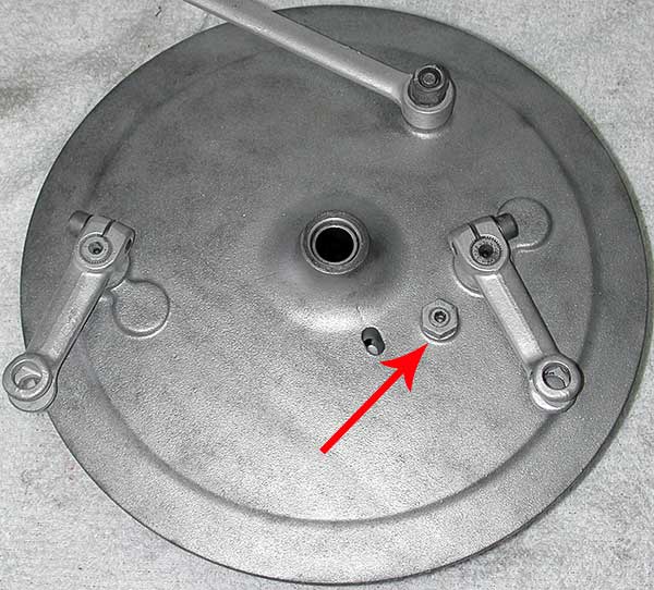
Here’s the other side of that adjustment bolt is an eccentric head or cam that limits the resting position of the lower shoe.

On the left side of the shoe you can see one of the two brake levers that expand the shoes. The front brake assembly is different than the rear, which has a single brake lever spreader. Here is one of the two front levers, disassembled for cleaning and lubing.
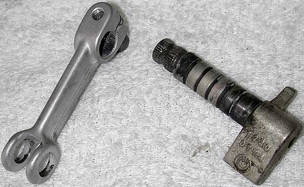
There was only dried black gunk in place of lube and they did not pivot as freely as desired.
I started to reassemble the parts and got stuck on the shoes. One end of each shoe slides over a post and each other end touches a spreader lever arm. One of my repair books just says to put the parts back on. The other book suggests having a helper. Well no duh! What it doesn’t mention is you and your buddy need to be gorillas. The spring force is high and you can’t use the v-snap trick that worked on the rear brakes. I grunted and sweated and bled and cursed. Then I got smart. Or so I thought.
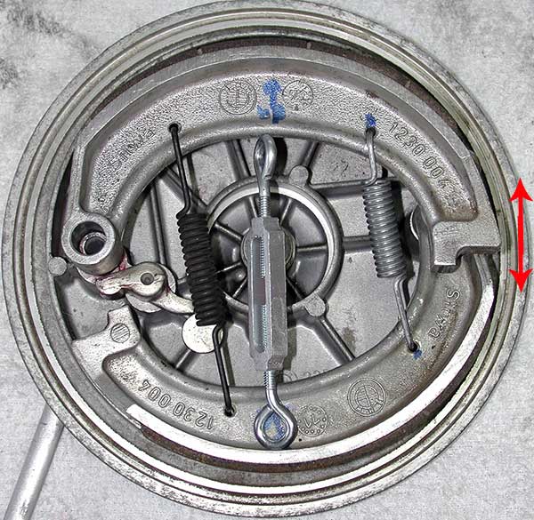
The double arrow shows where I needed to spread the right side of the shoes to get them re-mounted. The springs are intentionally not equal strength. I could spread the one on the left but not much of the right spring. So I tried making a turnbuckle spreader. I read about this somewhere and it seemed smart. I say “seemed” because since the left spring was weaker than the right spring all the spreader in the center position would do was to expand the left spring, not the right. Now I could have anticipated this instead of spending the time to measure and buy turnbuckle parts and machine some flats on the ends for safety and then feel smug… but I didn’t. I sort of deflated when the wrong spring started expanding.
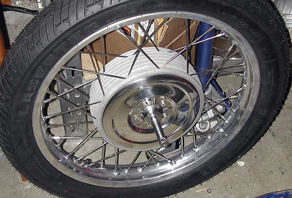
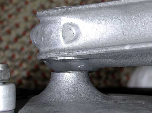
I was especially keen to get the brakes assembled because the rest of the front wheel is ready. The seals from Hammersley arrived Friday, about two weeks after I ordered them. And after tapping the seals with “top hat” spacers in place it seemed my wheel hub was okay. I balanced it with a half-ounce of weight and it seems ready to roll (literally).
The spacers were ‘proud’ of both sides so I figured the hub assembly would be trapped and loaded correctly. The left side is pressed by the axle inside the reducing sleeve while the right side is pressed against center of the brake assembly. So I needed the brakes done before I could, at last, put the front wheel on the bike. And it did not seem possible to remount the brake shoes myself. I tried a few other widgets I have in the garage like woodworking clamps and a ratcheting tie-down but I just couldn’t get the right grip on the shoes.
You know what I do at times like this? That’s right, I call BMW Joe and bring him the parts like some sort of offering to the mechanic deity. I just have to strike the right note of pitiful helplessness on the phone. Last night, late at night, Joe’s old daschund Rusty heard a noise in the yard, dashed outside, and promptly got sprayed by a skunk. Now this happened right outside the bedroom and Joe heard the commotion. So naturally he opens the door and in rushes Rusty. Woken in the middle of the night that seemed like a reasonable thing to do but he was still getting an earful about the interior house-stink from his wife Mary when I drove over this morning. I got a whiff of skunk in the driveway. I at least had the courtesy to ask if he needed me to bring more tomato juice with me (folk remedy for skunk stink, thankfully I never had to try it myself).
Joe’s technique for the brakes made worked fine. First he removed the weaker spring and seated the two shoes against each other. The brake expanding levers eventually need to fit in between them but that comes later. This was just positioning to get both shoes started on the posts.

This gets the shoes easily mounted on both posts. Then a pry bar can be used to expand the shoes enough to drop down over the expanding lever.

The other side can be dropped over the lever almost by hand since only the one strong spring is in place. Then both shoes can be tapped all the way down (a spring clip on top of each post keeps everything in place). We agreed there is probably a BMW tool for expanding the shoes properly but this technique seems reasonable. If you do this, make sure your pry bar is touching the very bottom of the thin casting as shown. Otherwise it might put too much stress on that thin wall.
The last step is to load the second, weaker, spring. The placement of these springs is critical. If you mix them up the brakes will function but not well.

This picture shows a special spring tool Joe had but we ended up using a plain Vice Grip to pull it up into the hole. If you’ve got a better technique then go ahead and post a comment and/or link. Might save the next wannabe mechanic the grief it caused me.
So I drive home with a goofy grin on my face because I’m looking forward to mounting the front wheel. I insert the brakes into the wheel. Everything is good. The brake hub is pressing on the wheel hub spacer and there is a tiny clearance for the wheel to spin freely against the brake. Looking good. So I put the wheel on my feet to lift it high enough to thread the axle into the fork and —
There is a gap on the right side. And it sort of makes sense that I’m missing a spacer. The wear pattern and ‘proud’ surfaces suggest I’m missing a spacer. The brake’s outer hub sleeve is recessed slightly from its casting face so it will not be pressed against the wheel hub properly without a spacer. The thing is, I can’t find the spacer. This is not the sort of part I figured I’d lose. I search through all my loose parts and I’m not finding it. This is just not possible. It is a relatively big part, not just a thin washer. How could this happen? Surely when I took the wheel off and it fell off I carefully placed it on the axle (or not)? What quantum singularity snuck into my garage and sucked up that particular part? Just not possible. Aargh!
You know what I do at times like this? When the going gets tough, the wimpy go and do what they’re good at. So I polished up some more parts. It was time to mount the front fender anyway since the wheel would make that much more difficult, if I ever figure out how to mount the wheel. The thin chrome fender strut was heavily rusted —
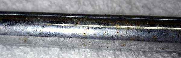
I may end up replacing this part later but it did clean up reasonably well with Nev-R-Dull wadding.

Here’s how the front end looks after I mounted the fender —

And I got to cleaning up the four turn signals.
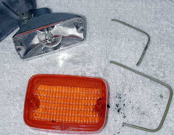
I had to scrape off the old white gaskets. My replacement gaskets are black and seem to be a different material. Note there is a small intentional gap in the gaskets at the bottom center of the lens to allow condensation to drain (I assume that’s why). I also replaced the individual black gaskets on the lens screws (and cleaned rust off the screw heads) but first I had to remove the old gaskets, which each formed a melted flat ring on the lenses. Lots of careful scraping and cursing. I cleaned up my bulb reflectors but a couple of these chromed-plastic parts are starting to show signs of age. The lenses cleaned up with some Novus plastic cleaner. One needed more work with Blue Magic plastic polish to remove surface defects.
I bought a new front turn signal harness. It came with crimped spade connectors that don’t work with the original press-clamp widgets on the back of the turn signals (must have changed in later years?). That was easy, I just cut off the spades and stripped a tiny length of insulation off each end. Now I hit my next “that’s not possible” moment. I have very few references for how the various wiring bits are supposed to be routed but I think this is not right —

This is the underside of the left turn signal, showing the harness coming out of the signal mounting stalk or ring on the fork. I could be wrong but I think the harness is supposed to run up through the black fork sleeve just above the signal’s stalk. The sleeves have the headlight bucket “ears” welded on them. That would hide the harness until it reached the headlight bucket. But that is full of fork, isn’t it? How are you supposed to thread the harness through there? That’d also require me to remove the triple tree top plate AND likely remove the upper fork leg. Uh uh. Now that I’ve got the forks sort of aligned that’s just not happening. There are also grommets on the harness suggesting what I’m thinking.
So can someone with an intact /5 tell me, did I screw up the harness run already? Is there an easier fix than what I’m thinking of?

I, uh, found the spacer late last night. D’oh! More in my next regular update.
Comment by penforhire — July 2, 2007 @ 7:13 am
On my /5 the turn signal wires run through a hole on the inside of the headlight ear sleeve, then down the sleeve and exit through a notch at the top of the lower triple tree clamp and under the signal bracket to the light. Very neat and clean and can’t be seen unless you stick your head under there.It appears as though you would need to do a bunch of disassembly to do it properly, but hell you’ve come this far so IMO you should go for it. Hope this helps. God only knows you’ve helped me. You are doing excellent work which will be invaluble to me and others in the future. Thanks! Tom
Comment by Tom Traina — July 7, 2007 @ 9:12 am
I know it’s too late, but here’s a method for stretching springs like you needed with your brake — use a handful of pennies! Bend the spring back and forth, adding a penny to each space between coils, until you have the spring elongated and full of pennies. Then install it and pull the pennies with a pliers….
Comment by phil — July 23, 2007 @ 8:12 am
Not too late for me though! Very helpful page and this comment saved me a ton of grief. That 2nd spring popped right in.
Comment by Larry — March 10, 2014 @ 6:06 am
Let’s just say a guy marked some parts, but the markings mysteriously rubbed off and how he doesn’t know which way is up. How do I…er, this person…how would HE get his brakes back together?
Comment by Shaun — July 2, 2009 @ 10:40 am
Shaun, ha, ha. Tell your, um, friend to look closely at the photos in one of the repair manuals and here in my blog. You should be able to muddle through it. The trickiest part was the spring ID, as I noted in the blog. And I put the whole thing in backwards (again as noted) and it wasn’t so hard to re-do. Just check the pedal action before you re-mount the rear wheel.
Comment by Penforhire — July 6, 2009 @ 6:42 am
I just replaced the brake shoes on my R75/5 and an easy way to get the springs on is to put them on both shoes (ie – complete the shoe assembly off the bike), set one shoe on the post and gently pry (I used a long open ended wrench) the other shoe to the post. It went on quickly and easily. This method also works well on older cars with drum brakes.
Comment by ken — June 10, 2011 @ 11:48 am